
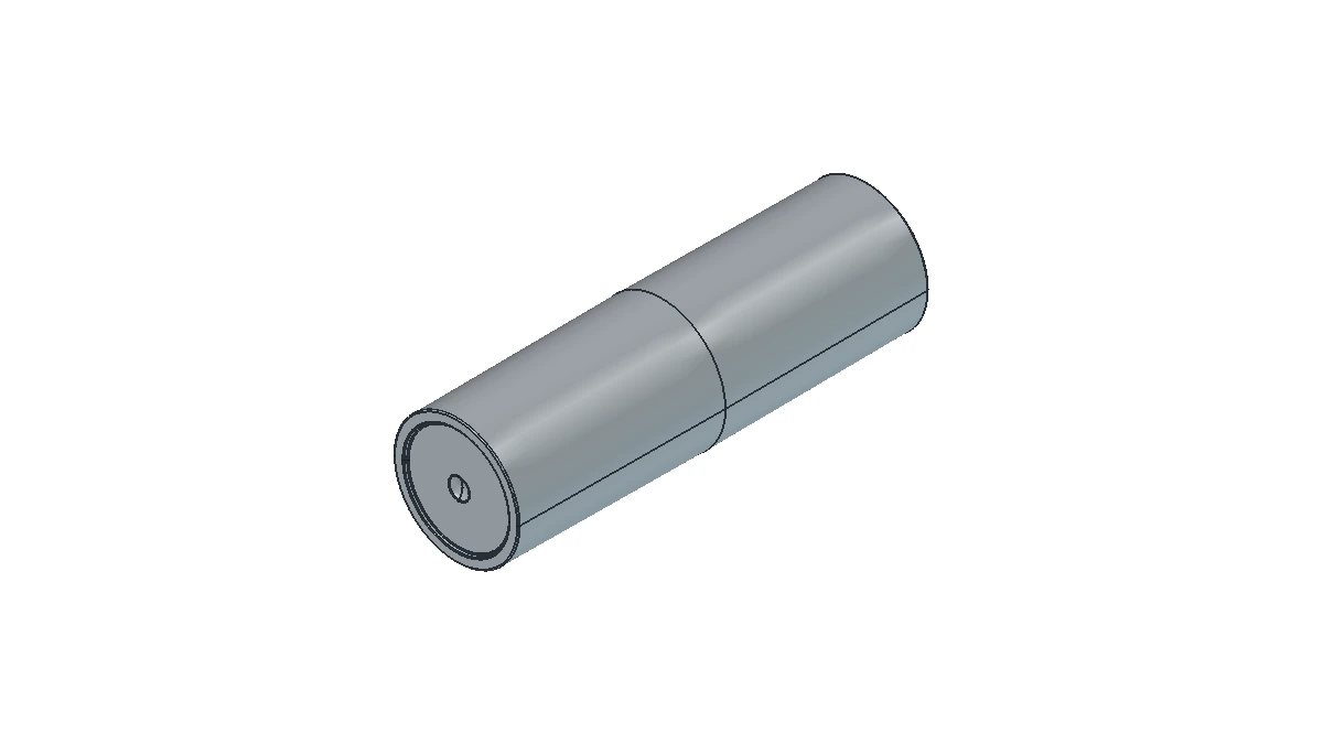
When examining samples of Lipstick Tubes, the cap, overall shape, and surface finish are easy to identify. Remove the cap and twist the base, and the lipstick extends. In packaging development, however, identifying which parts shape the appearance and which raise and lower the lipstick requires a look inside.
A typical twist-up lipstick tube can first be grouped by function into external parts, such as the cap and base, and an internal lift mechanism. Taking the mechanism apart usually reveals a cup that supports the lipstick, a guide sleeve with straight slots, and a sleeve with helical grooves. Depending on the design, decorative sleeves, inner caps, magnets, or weight inserts may be added. The actual number of parts varies.
The example below explains how these parts work together in a mechanism where pins on the cup engage both straight slots and helical grooves. This breakdown does not apply to other drive mechanisms.
The structural illustrations use Sambound’s YR1022 stock-mold design to show the components and assembly relationships of this type of lipstick tube. The shape, combination of parts, and connections vary between designs. Colors distinguish the parts in the illustrations and do not represent actual product colors or materials.
Separate the Outer Packaging from the Internal Mechanism
The outer shell and internal mechanism are two levels of a lipstick tube’s structure. External parts surround the mechanism and serve as the closure, grip, and visible exterior. The mechanism supports the lipstick and extends and retracts it. This grouping explains their functions and should not be treated as the manufacturer’s actual parts list.
| Part or assembly | Location | Main function |
|---|---|---|
| Cap | Over the upper part of the tube | Covers the lipstick and tube opening, closes against the tube body, and contributes to the appearance |
| Base or lower tube | Lower part of the tube | Holds and connects the internal assembly and forms the area held or twisted during use |
| Outer sleeve or decorative ring | Around or attached to the outside of the tube, depending on the design | Creates the shape, color, and decorative finish; some also connect to the internal mechanism |
| Lift mechanism | Inside the tube | Supports the lipstick and extends and retracts it through the interaction of internal parts |
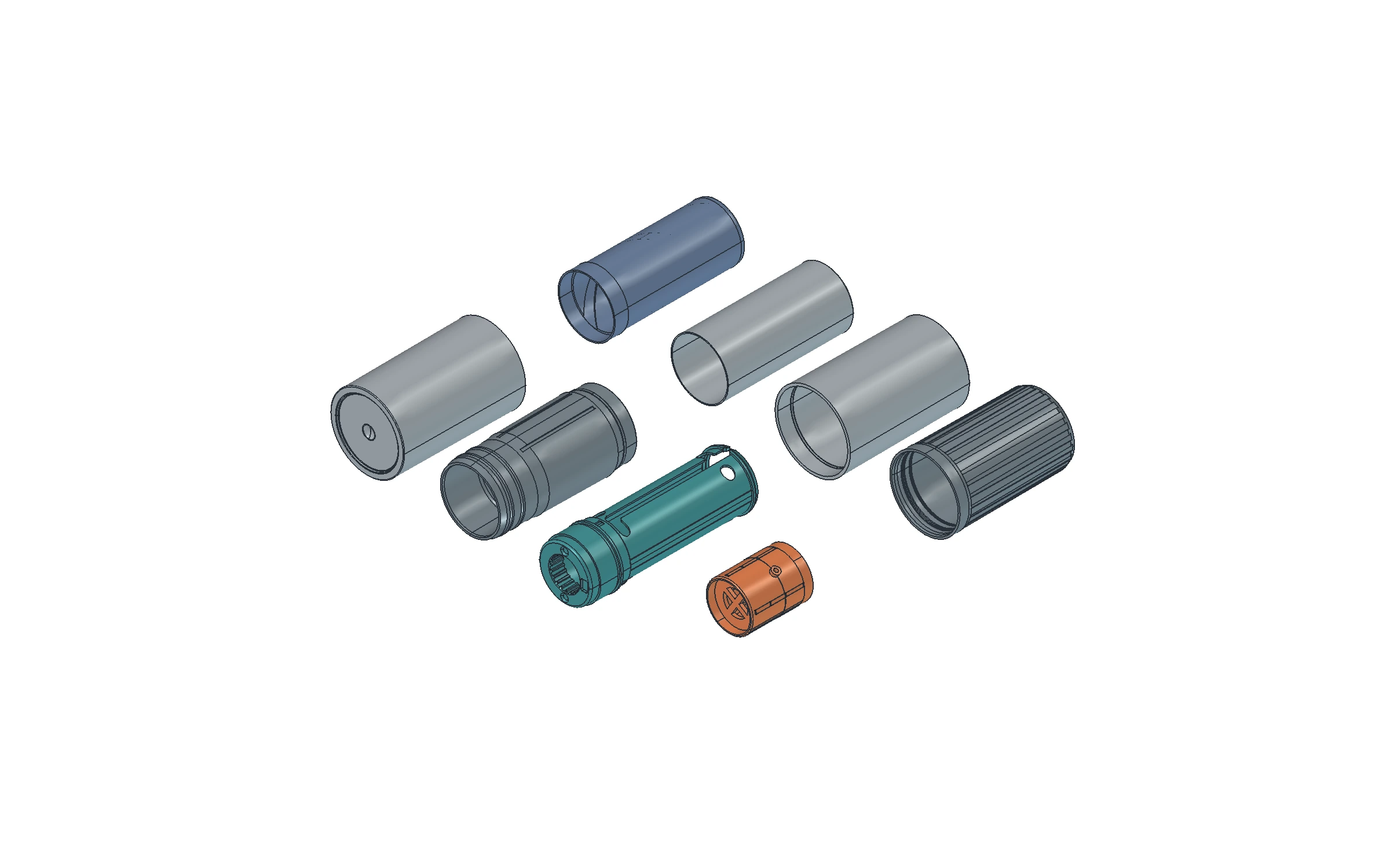
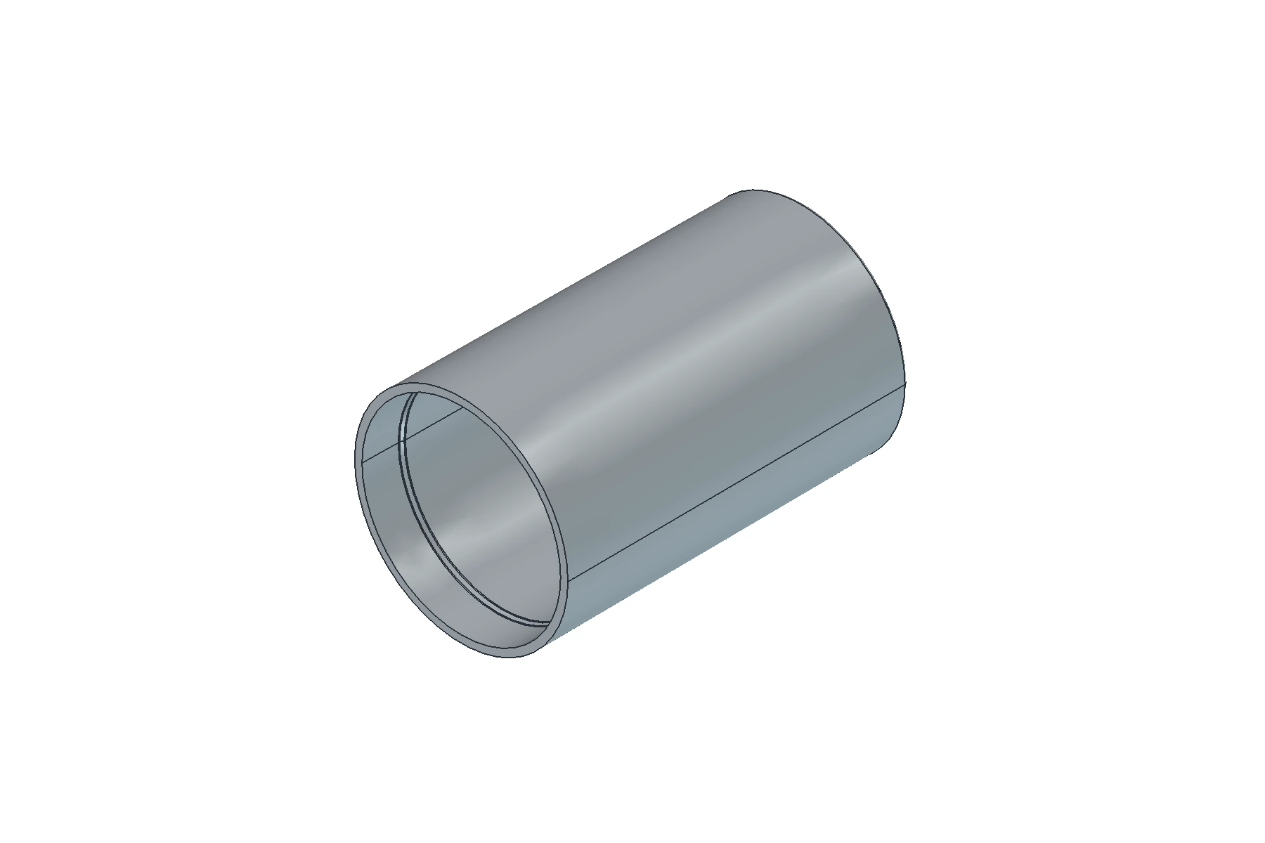
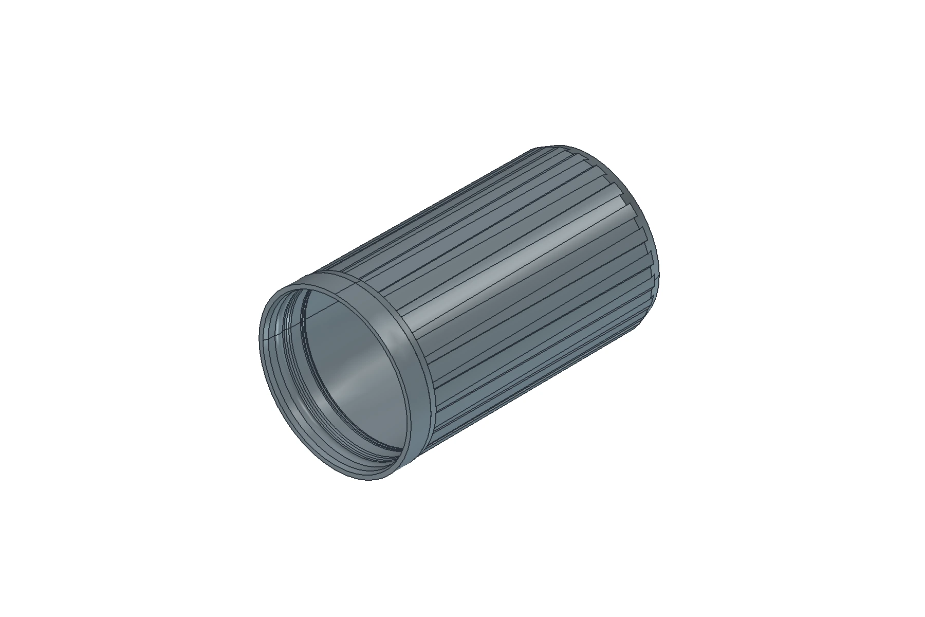
Some drawings call the outer barrel sleeve the zhongshu. The outer barrel sleeve and the internal mechanism should not be treated as the same part based on their names alone. In the structure used here, the outer barrel sleeve surrounds the spiral sleeve, while the internal mechanism is the assembly that supports and drives the lipstick. The outer barrel sleeve may also be included in that assembly, so the outer sleeve and mechanism are not necessarily two separate groups of parts. When reading a drawing, check the location and assembly relationship of the part to which each name refers.
The cap is not necessarily a single part. The visible cap shell may contain an inner cap or a mating part. Similarly, the base may combine an outer shell with an inner base insert. A continuous exterior does not necessarily mean a single item in the parts list.
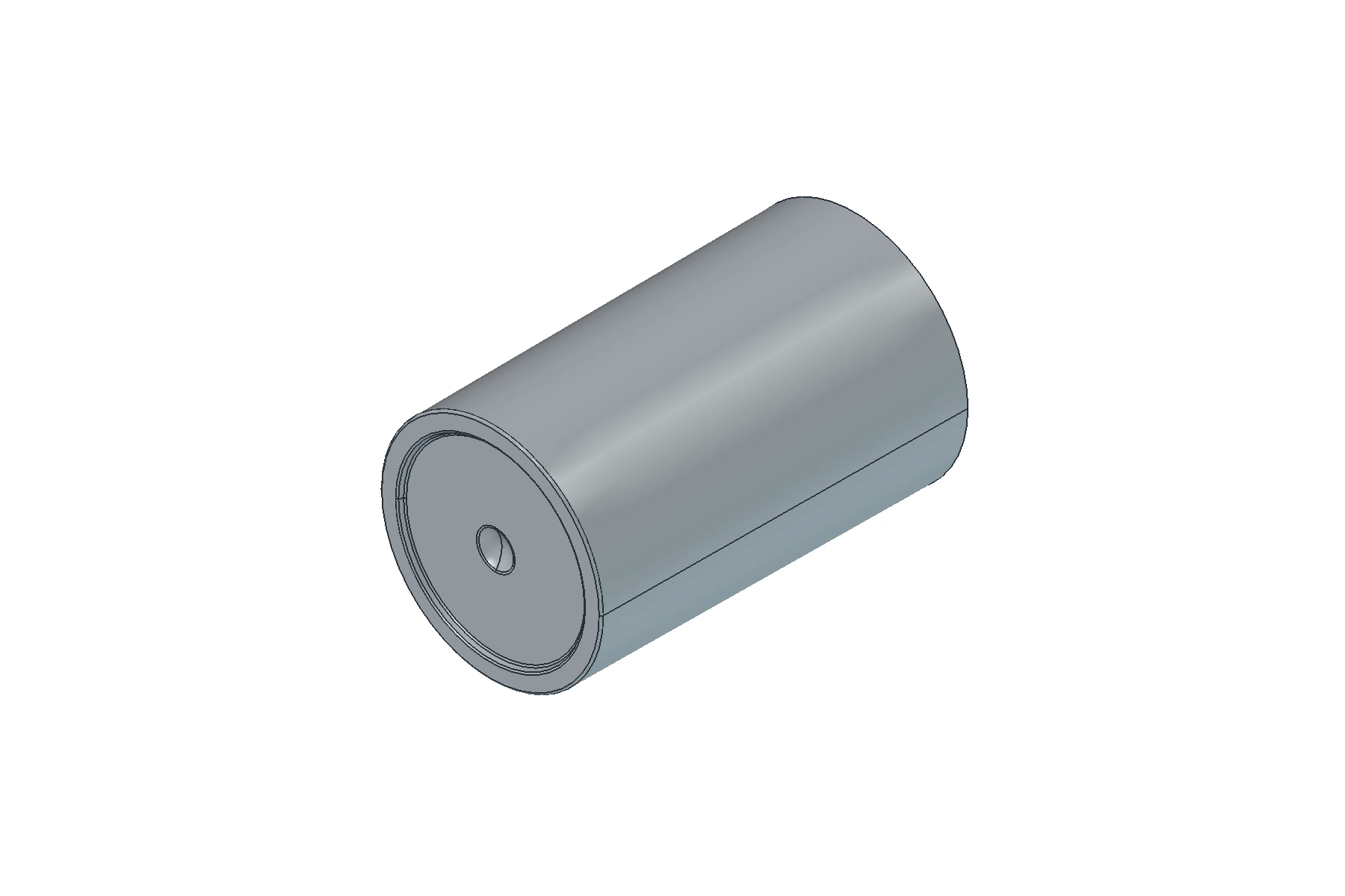
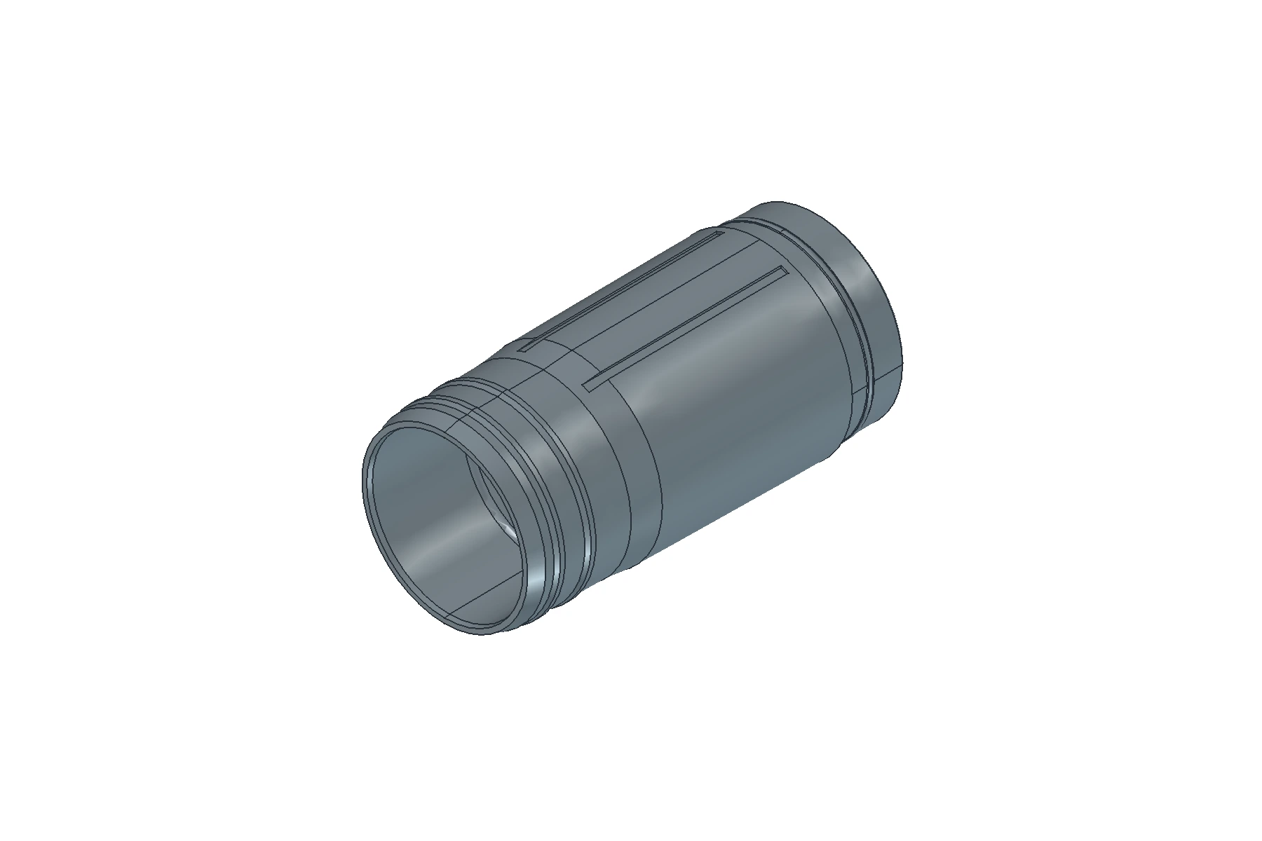
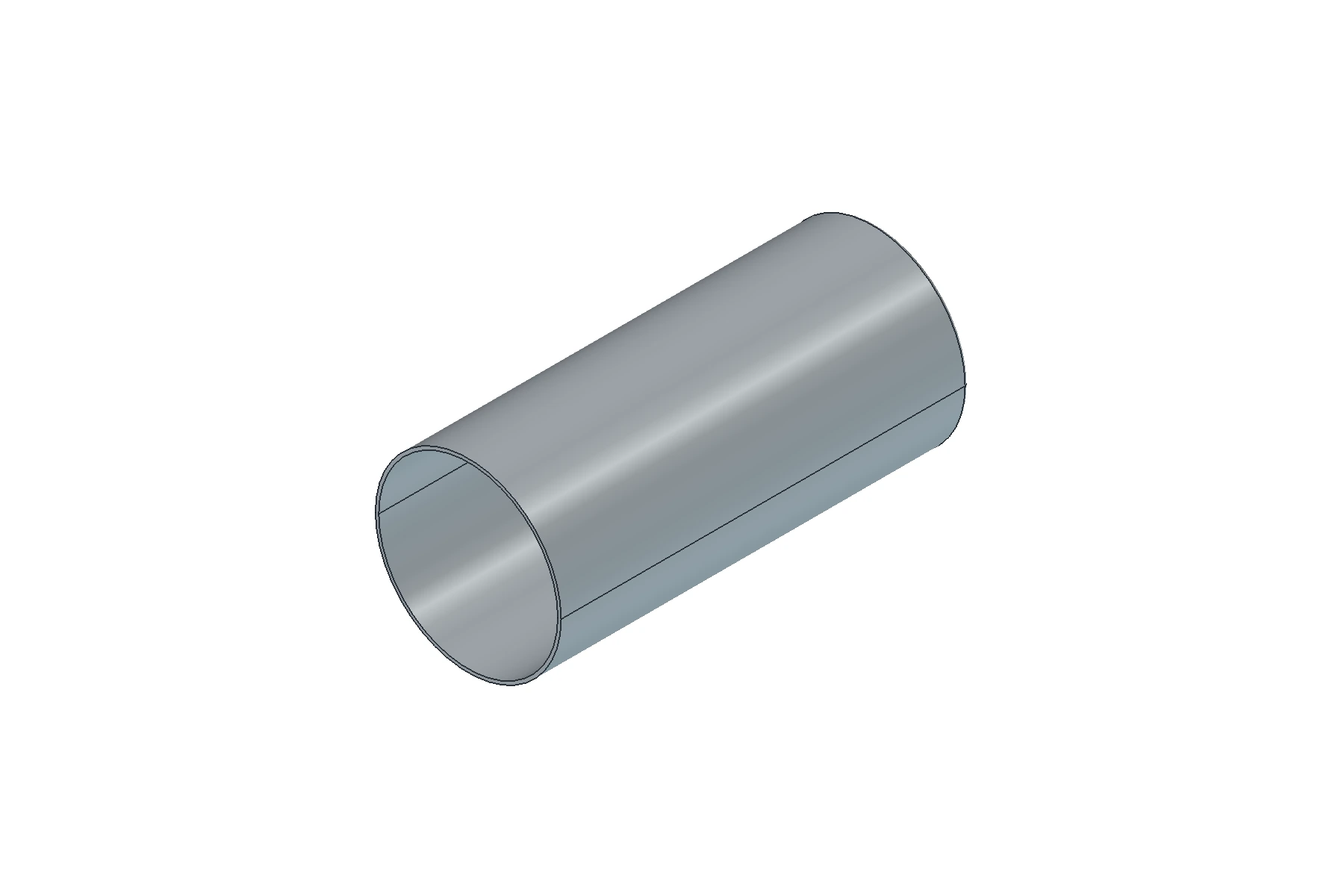
Functions of the Three Main Parts in the Mechanism
Cup: Supports the Lipstick
The Chinese industry term zhuzi refers to the supporting cup. It holds the bottom of the lipstick and moves it up and down. The cup is a packaging part, while the lipstick is the contents. They should be considered separately.
In this example, the cup has outward projections on its sides, also called pins. They engage grooves in the surrounding sleeves so that relative rotation between the two sleeves raises or lowers the cup. Each pin is part of the cup’s structure, rather than a separate pin inserted into the lipstick.
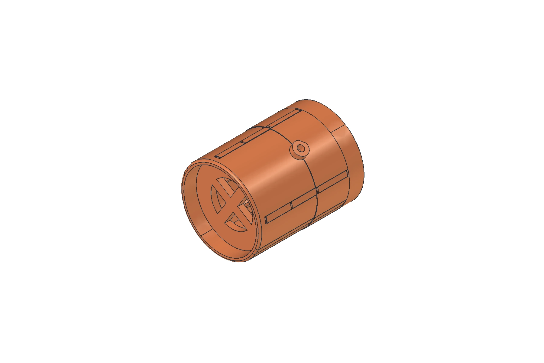
Guide Sleeve: Constrains the Cup’s Direction of Travel
The part called chazi, or fork, in Chinese industry terminology is a sleeve with axial guide slots in this example. Axial means along the length of the lipstick tube, which is also the direction in which the slots extend.
The cup’s pins pass through the guide slots. The slot walls prevent the pins from moving around the sleeve, allowing the cup to travel mainly along the length of the guide sleeve rather than freely rotating with the spiral sleeve. The guide sleeve guides the cup. It is not a bracket that extends out of the tube opening with the cup.
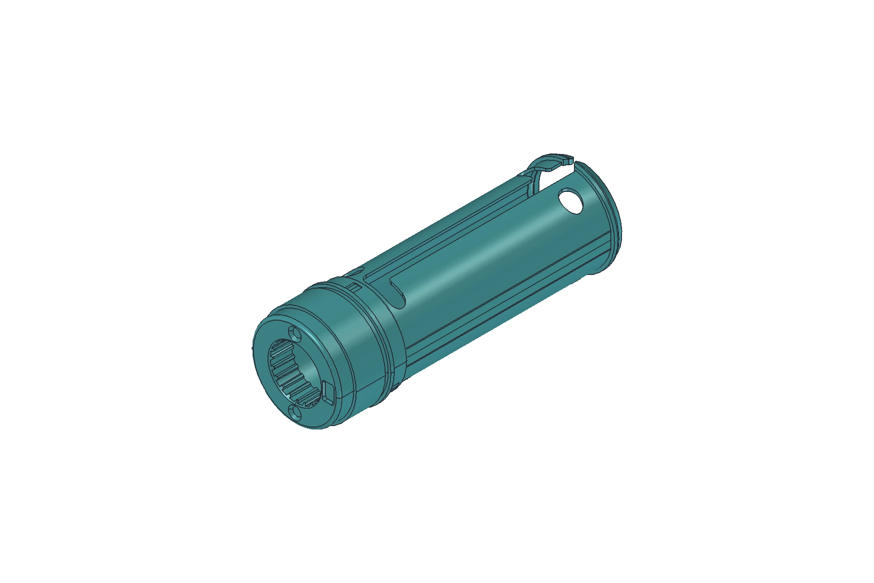
Spiral Sleeve: Converts Relative Rotation into Axial Movement
The spiral sleeve surrounds the guide sleeve. Its inner wall contains helical grooves that wind around the circumference while changing height. After passing through the straight slots, the cup’s pins extend into these helical grooves.
As the two sleeves rotate relative to each other, the straight slots and helical grooves constrain the pins together. The straight slots restrict movement to the axial direction. The helical grooves change the height at which the two paths intersect as rotation occurs, raising or lowering the cup.
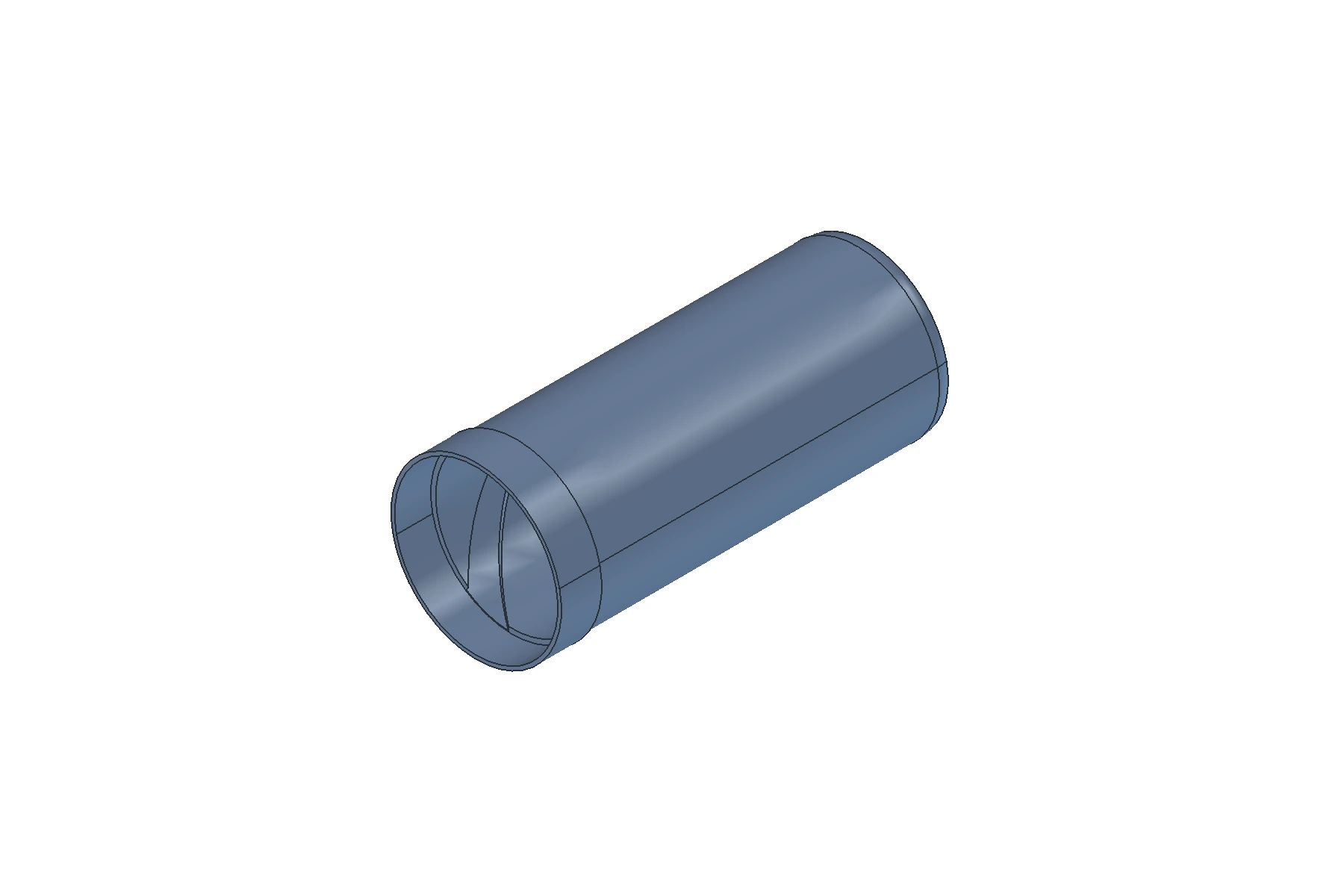
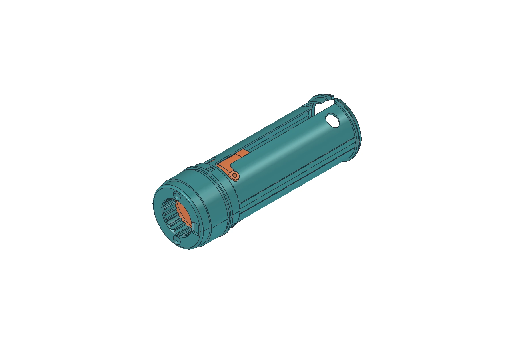
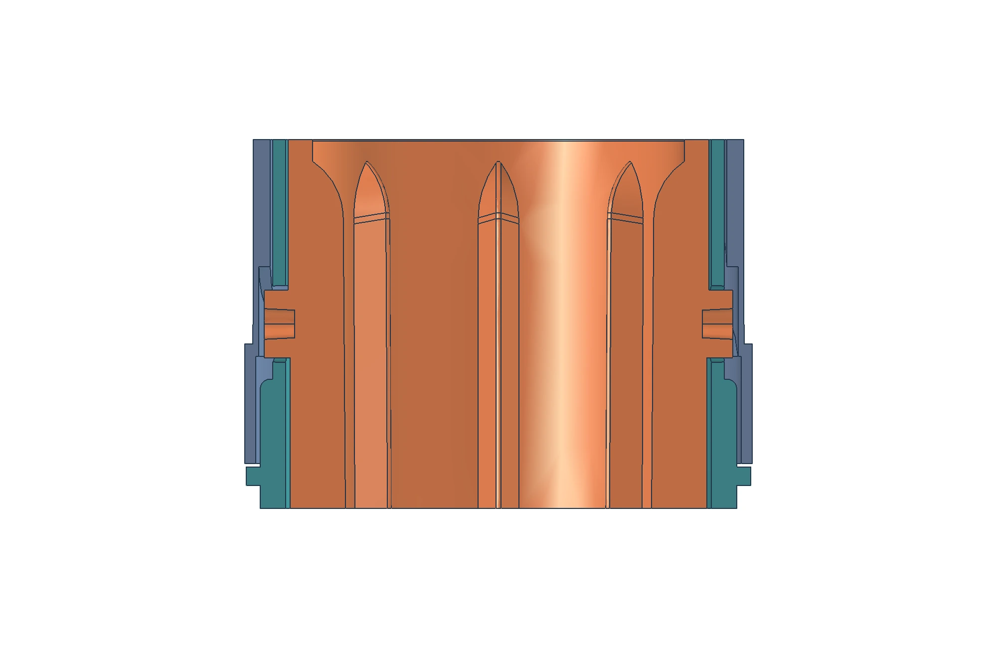
Cup, guide sleeve, and spiral sleeve are common names used to understand this type of mechanism. They do not mean that every lipstick tube has exactly three internal parts. Additional connections, stops, and sealing structures must be identified for the specific design.
How Twisting the Tube Raises and Lowers the Cup
First, treat the guide sleeve as a stationary reference and rotate the outer spiral sleeve. The cup’s pins remain in the guide sleeve’s straight slots while also staying inside the helical grooves.
When the spiral sleeve turns through an angle, the height of each helical groove changes at the position of the straight slot. The pin cannot move sideways through the slot wall, so it moves up or down along the slot, carrying the cup and lipstick with it. Turning in the opposite direction reverses the height change at the intersection, retracting the cup along the same path.
This arrangement also needs to limit axial separation between the two sleeves. They must be able to rotate relative to each other without being carried out of the tube opening with the cup. The arrangement of retaining rings, shoulders, and other stops depends on the design.
During use, which internal sleeve connects to the base and which connects to the outer sleeve affects which part appears to rotate. The statement that the cup does not rotate therefore needs a reference: in the straight-slot guide structure described above, the cup is constrained against rotation relative to the guide sleeve. If the guide sleeve turns with the user’s hand, the cup may turn with it. Relative rotation between the two sleeves is what raises and lowers the cup.
This explains why the outer shell’s color or a single photograph of a closed tube reveals little about its internal lift mechanism.
Are Magnets, Weight Inserts, and Seals Present in Every Tube?
These parts serve different functions and are fitted according to the product design. They should not be combined into a fixed parts list for all lipstick tubes.
| Optional part or structure | Main purpose | Distinction to keep clear |
|---|---|---|
| Magnets and mating parts | Help the cap close magnetically | A magnetic closure does not establish airtightness |
| Weight inserts | Increase packaging weight and adjust the feel in the hand | May be placed in the base or cap according to the design; they do not raise or lower the cup |
| Sealing rings, inner caps, or mating sealing surfaces | Form a seal at the relevant interface | Sealing structures vary; a tight-fitting cap alone does not establish sealing performance |
| Connections for a replaceable mechanism | Allow the used mechanism to be removed and replaced as designed | Extending the lipstick by twisting and replacing the mechanism are two different functions |
For example, YR1049 on Sambound’s website is a magnetic lipstick tube. Magnetic refers to the closure method. It does not establish that this design also has a replaceable mechanism, additional weight inserts, or airtight performance. Each of those functions needs separate verification.
A seal is not always a separate rubber ring. Some designs use a separate elastomeric sealing ring. Others use a sealing ridge on the inner cap or inner base that mates with an adjacent part. To assess a specific lipstick tube, identify the actual sealing contact surfaces and check the corresponding product tests.
To understand the structure of Lipstick Tubes, start with the cap and base to see how the tube closes and is held. Then follow the internal mechanism to identify the cup, guide sleeve, and spiral sleeve. The cup supports the lipstick, the straight slots guide it, and the helical grooves change its position through relative rotation. Once these relationships are clear, the part names can be matched to their actual functions.