Why Lip Gloss Leaks Specifically at the Neck Threads
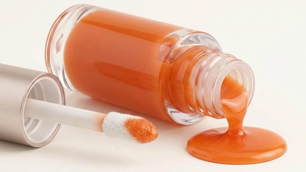
When summer arrives, customer leak complaints spike. The cap comes off, and the entire neck thread is coated in product, with excess formula pooling inside the cap cavity. Many brands instinctively tell their filling factory to torque the caps tighter. In most cases, thread leakage has nothing to do with the cap.
At Sambound, we have torn down dozens of leaking Lipgloss-Tuben. Thread-level leaks almost always trace back to two root causes: an improper interference fit between the wiper (plug) and the bottle neck, and shipping temperature spikes that stress that seal. The first issue originates on the production line; the second exposes it during transit. They rarely act alone.
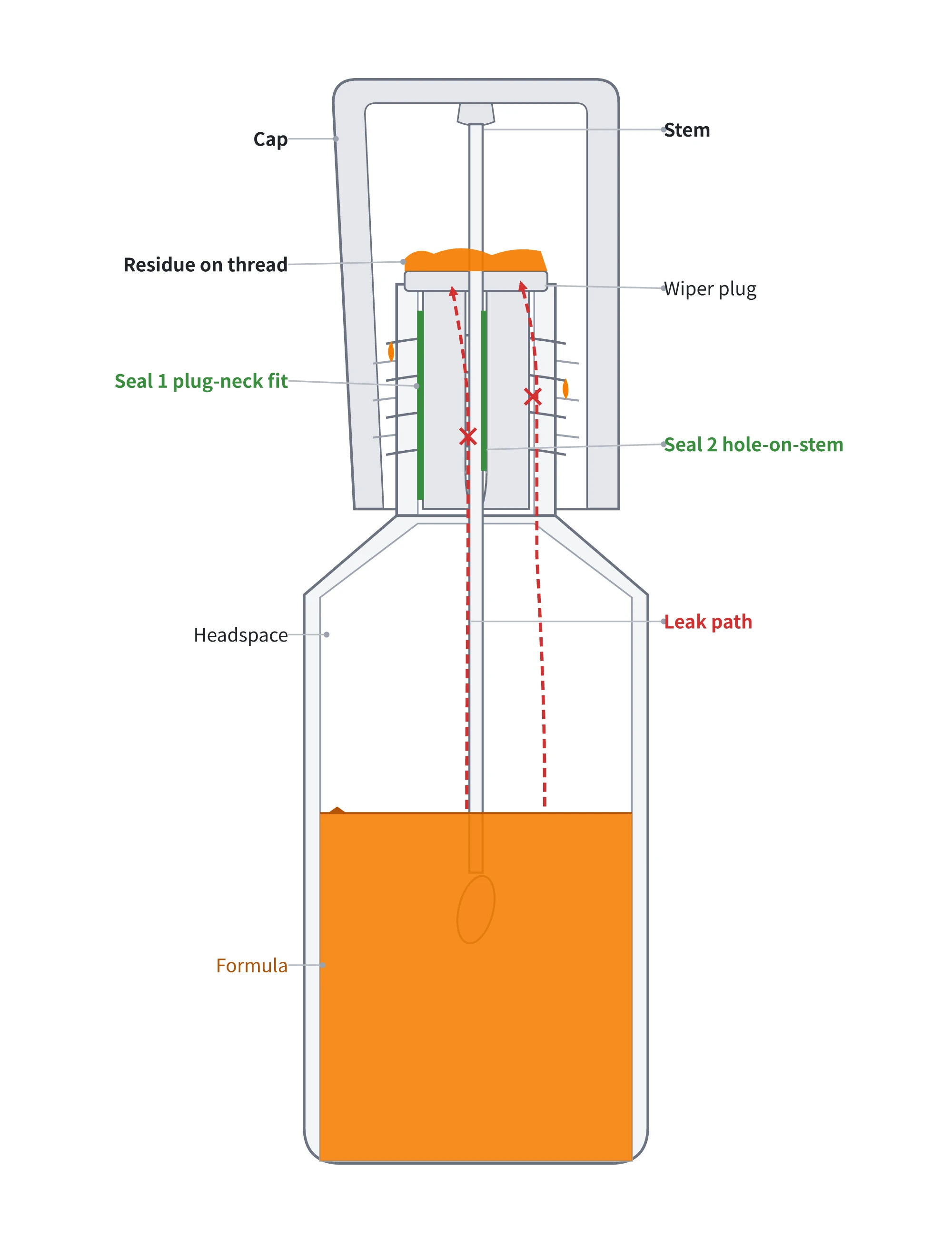
In a standard lip gloss package, two primary sealing barriers protect the neck threads from the bulk formula:
- First barrier: The outer wall of the wiper pressing against the bottle neck inner diameter (ID). The wiper outer diameter (OD) is slightly larger than the neck ID. Pressing it into place creates elastic contact pressure, locking the formula below the plug.
- Second barrier: The central orifice of the wiper hugging the applicator wand. When the wand moves in and out, the wiper scrapes off excess product while maintaining a dynamic seal.
The threaded cap is merely the third barrier. Its job is to prevent product that has already escaped past the wiper from leaking outside the package.
Formula pooling at the neck threads is direct proof that the product has bypassed the wiper. The threaded neck is an open cavity with no internal barrier. If bulk formula reaches the threads, investigate the wiper-to-neck interference fit first, check shipping temperature exposure second, and examine the cap last.
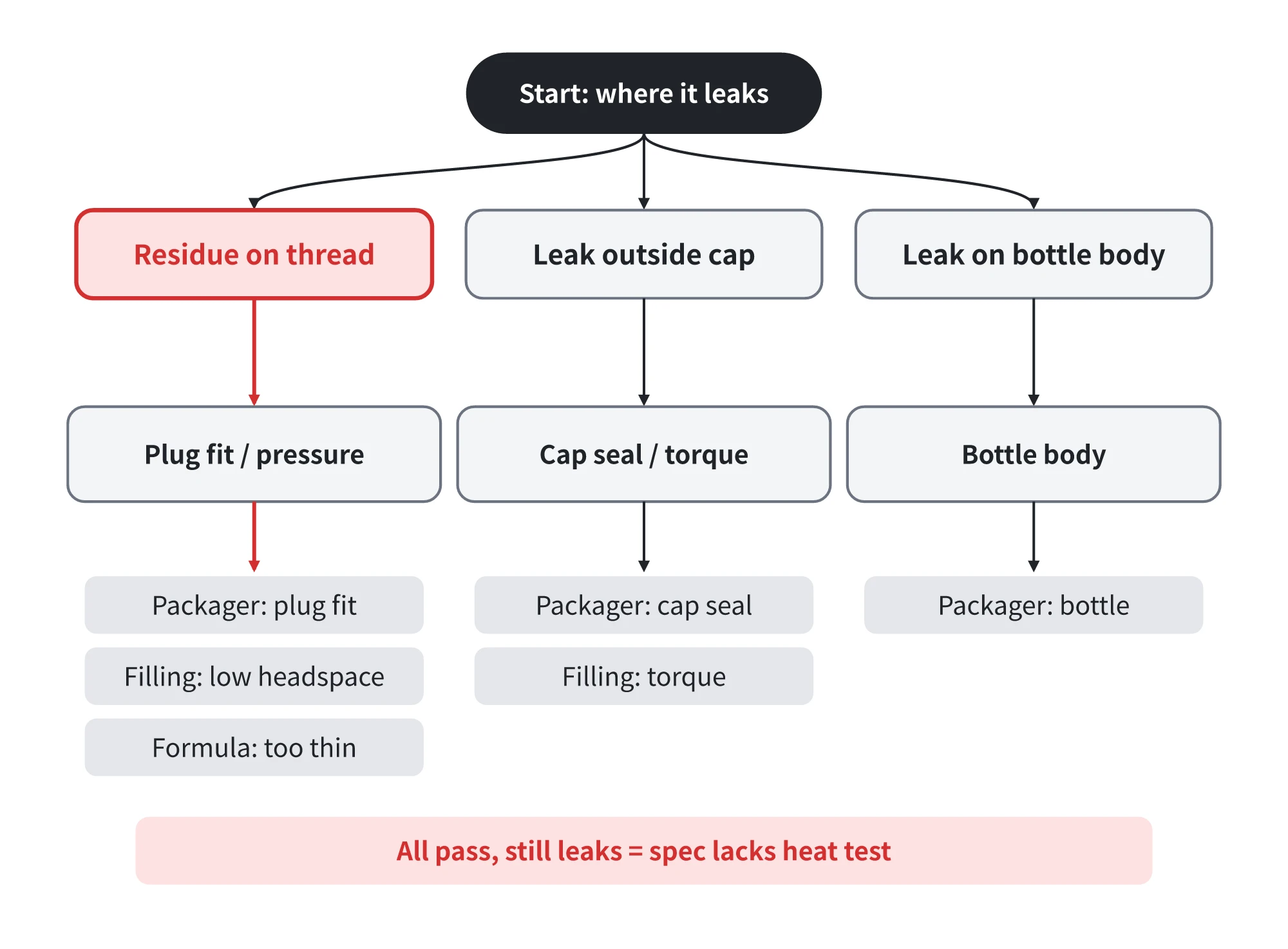
Different leak locations point to different failure modes. Product accumulating on the threads and inside the cap indicates wiper seal failure or excessive internal pressure. Product beading on the cap exterior or leaking at the parting line indicates cap liner defects or false torquing (where the cap feels tight but has not fully engaged the sealing seat). Container wall leaks point to bottle molding defects. Solid lipstick bullets do not flow on their own, but low-viscosity lip gloss formulas migrate through micro-gaps under pressure. This makes sealing tolerances for lip gloss packaging far more critical than for lipsticks.
Too Little Wiper Interference Causes Leaks, but Too Much Creates New Problems
Interference fit refers to the dimensional difference between the wiper OD and the bottle neck ID. When inserted, the wiper wall compresses elastically against the inner neck wall, generating radial contact pressure that blocks formula migration. If this interference is too small, contact pressure drops. Under heat and transit vibration, the formula seeps upward around the outer wiper wall, or the wand pulls the entire wiper out during use.
Wipers typically use one of two material categories: low-density polyethylene (LDPE), which is cost-effective for high-volume production, or thermoplastic elastomers (TPE) and nitrile rubber, which offer superior elasticity at a higher cost. Rubber plugs seal reliably but require an extra retention ring, increasing assembly cost. LDPE is stiffer, so mold designers thin out the scraping lip (typically 0.2 to 0.4 mm) to achieve elastic sealing. A well-designed wiper balances a rigid structural body with a flexible scraping lip.
Tighter is not always better. Excessive interference causes LDPE to buckle or seat improperly during automated insertion. If the wiper hangs crooked inside the neck, effective contact pressure drops, causing immediate leaks. High interference also increases wand extraction force, strips doe-foot applicator flocking, and reduces product dosage with every stroke. Furthermore, when an oversized wiper forms an airtight seal before full insertion, inserting the wand compresses trapped air and formula. Without an engineered air-vent channel along the wiper lip, this pressure spike will eject formula outward when the consumer opens the component.
How to Calculate and Validate Wiper Interference Fit
The packaging industry has no single, universal standard for wiper interference dimensions. Most toolmakers rely on generic rules of thumb. However, production specifications require precise engineering limits rather than vague assembly instructions.
Defining interference is challenging due to tolerance stack-up. The nominal interference on a technical drawing is an ideal value. Injection molding tolerances for the bottle neck ID (often around ±0.15 mm) combined with wiper OD tolerances can consume up to half of the intended interference in a worst-case scenario. Similar to elastomeric O-ring design—where a 0.3 mm stack-up can cut theoretical compression in half—bottle-and-wiper assemblies require strict tolerance budgeting.
Interference fit operates within a defined window. In static elastomeric seals, standard engineering guidelines target 15% to 30% compression. Too little compression causes leaks; too much leads to plastic deformation and assembly jamming. To lock down this window, follow three verification steps:
- Tighten the tolerance chain: Specify bottle neck ID and wiper OD tolerances simultaneously during design review. Use MT3 injection molding tolerance standards, holding critical neck dimensions to ±0.05 mm to protect nominal interference margins.
- Verify three-point physical seating: Ensure the wiper fully seats across three contact points: the elastic wiper skirt flush against the bottle shoulder, the top flange flush against the neck rim, and the retention ribs locked securely into the bottle internal undercut.
- Validate functional performance: Test extraction force, flocking retention, and inverted leak resistance with production formula. The assembly is production-ready only when all three parameters pass.
At Sambound, when engineering secondary silicone gasket seals for custom closures, we validate 0.2 mm interference through 100 thermal cycles (-20 °C to 45 °C) while maintaining a process capability index (Cpk) ≥ 1.33. An interference fit must be calculated, tested, and controlled across mass production.
What Really Happens Inside a Shipping Container in Summer
The second root cause occurs during ocean freight. Summer export shipments frequently sit inside ocean containers for two to three weeks. Field measurements by the German Meteorological Service (DWD) in Hamburg show that under 25 °C ambient sunlight, internal air temperatures reach approximately 50 °C in brown steel containers and 38 °C in white containers.
For a filled lip gloss container, 50°C creates substantial hydraulic stress. Cosmetic oil phases expand by roughly 0.07% per 1°C increase, whereas plastic packaging expands by only about 0.01% per 1°C. As container temperatures climb from 25°C to 50°C, bulk formula volume expands by roughly 1.7%, while the bottle interior expands by only 0.2%. This excess volume compresses the air layer above the fill line (headspace), driving up internal container pressure.
Headspace serves as a critical pneumatic cushion. If a bottle is overfilled and lacks sufficient headspace, volumetric expansion transfers hydraulic pressure directly against the weakest barrier: the wiper-to-neck interface and the wiper orifice. Compounding the problem, LDPE has a heat deflection temperature (HDT under 0.45 MPa load) between 40°C and 50°C. At 50°C container temperatures, the wiper softens, radial contact force relaxes, and plastic creep sets in under day-night thermal cycling. A marginal wiper fit will fail on its first ocean transit.
Passed Empty-Bottle Testing but Leaked at Port: Why?
Brands often wonder why packages that pass ambient, inverted leak testing at the factory arrive at destination ports covered in leaked formula. Ambient testing with empty or water-filled components fails to simulate transit realities. Without an actual formula, there is no volumetric thermal expansion, no pneumatic headspace compression, and no thermal material softening. Ambient testing only confirms that the wiper holds static fluid under ideal lab conditions.
Reliable shipping qualification requires robust environmental stress testing:
- Storage at 45°C for three months to project two-year ambient shelf stability.
- Thermal shock cycling across -10°C to 25°C (three 24-hour cycles per stage).
- Multi-axis orientation testing (upright, inverted, and horizontal) using production formula.
Manual shake tests provide a quick directional check, but automated vibration testing with preheated, filled components is necessary to replicate container transport dynamics.
Root Cause Analysis: Trace the Leak Before Assigning Blame
When investigating customer defect reports, follow a systematic diagnostic sequence before assigning vendor responsibility:
- Identify the leak origin: Product pooled at the threads points to wiper fit or internal pressure buildup. Product on the exterior cap surface points to cap liner defects or insufficient torque. Container wall leakage points to bottle molding flaws.
- Inspect retain samples: Place retention samples from the same production lot into inverted storage alongside warehouse inventory. If the entire lot leaks, the issue is systemic tool design or molding process drift. If only isolated units leak, investigate filling inconsistencies or transit mishandling.
- Replicate the failure mode: Subject retain samples to combined thermal cycling and inverted leak testing under the parameters below.
- Assign root responsibility: Defective wiper fit and improper plug insertion belong to the Kosmetikverpackungshersteller. Insufficient headspace and overfilling belong to the contract filler. Unstable volatility or excessive viscosity drop belongs to the formula development team. If all components meet nominal drawings individually but fail under transit, update the design specification to mandate pre-shipment thermal validation.
| Prüfmethode | Test Conditions | Inspection Criteria | Standard Reference |
|---|---|---|---|
| Low-Temperature Horizontal Rest | Store horizontally in a 4°C ± 1°C chamber for 24 hours; inspect immediately upon inversion. | No leakage at sealing interfaces; no cap cracking or structural distortion. | Industry standard protocol |
| Hydrostatic Seal Pressure | Submerge under water at 200 kPa for 1 minute, then ramp pressure to 350 kPa. | Zero bubble leakage; cap must not back off or dislodge. | Industry standard protocol |
| Thermal Shock Cycling | Cycle between -10°C and 25°C across 3 cycles (24 hours per stage). | Zero leakage across upright, inverted, and side-lying positions post-cycle. | Standard packaging protocol |
| High-Temperature Aging | Store at 45°C for 3 months. | Zero leakage; monthly formula weight loss must not exceed 1.0%. | Standard packaging protocol |
| Severe Transit Simulation | 100 thermal cycles (-20°C to 45°C) plus 24-hour inverted test on 100-piece first-article samples. | Process capability Cpk ≥ 1.33 across all critical sealing dimensions. | Sambound validation standard |
Thread leaks are fully preventable. Proper wiper interference secures the primary seal at the factory, while thermal cycling validation guarantees performance under extreme transit conditions. If you are troubleshooting a leaking lip gloss line, send your component drawings and physical samples to Sambound. Our engineering team will analyze the tolerance stack-up and verify whether the failure stems from wiper seating or unmitigated thermal expansion.