When a brand takes a product design to a packaging factory for a quotation, the question that causes the most trouble usually isn’t the price. It is this one: can this exterior structure actually be molded?
Many brands create product designs that look great. The shapes have distinctive curves, and the details are rich. But in many cases, the design overlooks whether the part can be released from an injection mold. In our more than 10 years of making Lipstick Tubes, Sambound has seen that only a small number of drawings can go straight into tooling. That usually happens only when the designer already understands injection molding. Most drawings need revisions first. The usual approach is to preserve the key design features, then optimize the structure without losing the original style. If the structure is not adjusted, it simply can’t be made by injection molding. The real issue is not appearance. It is whether the part can be demolded smoothly during injection molding and whether it can support a production-ready mold.
What Is the Difference Between Exterior Parts and the Inner Mechanism?
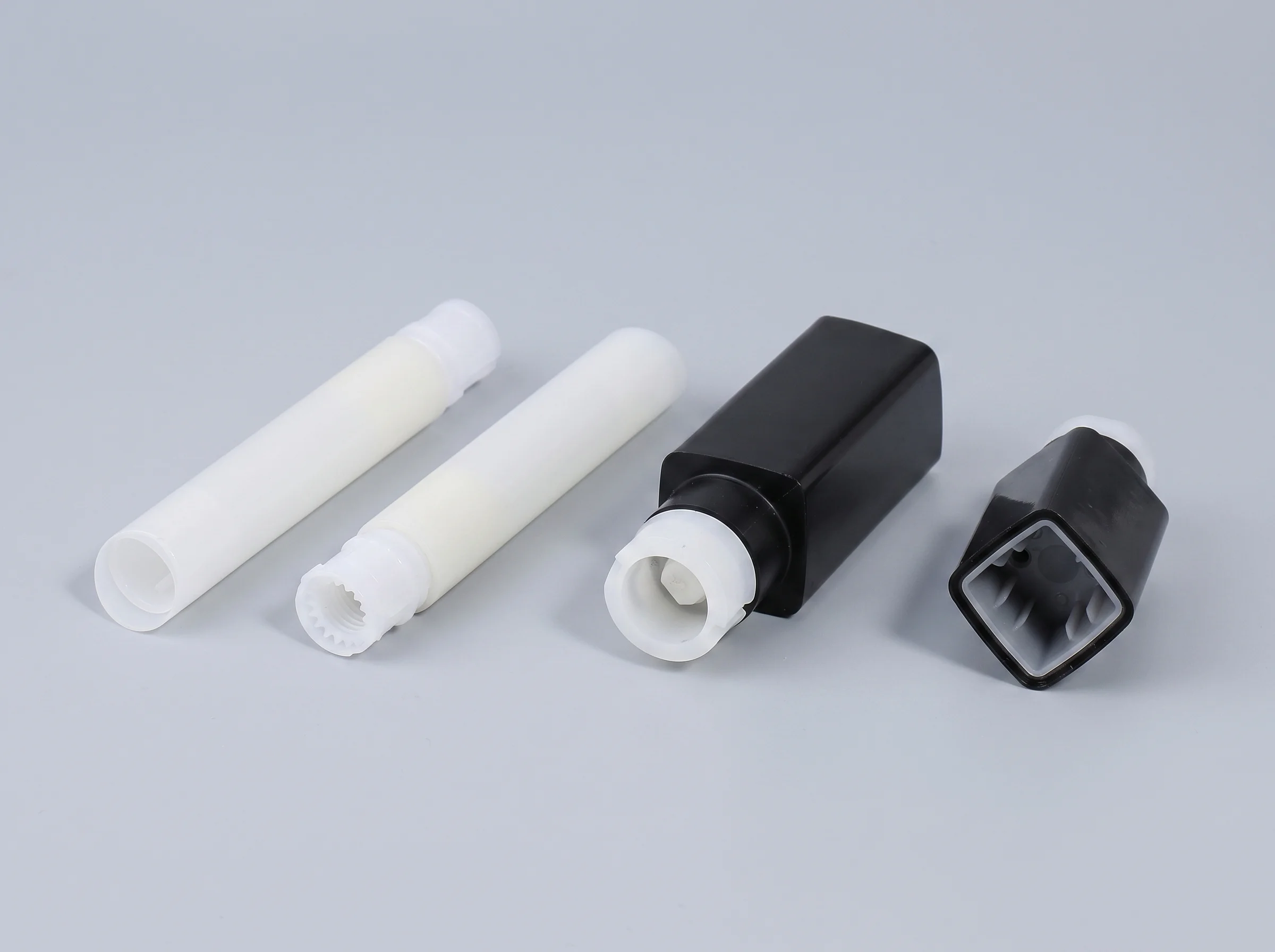
A lipstick tube looks like one product, but from a tooling standpoint it has two core systems. The visible outer shell, cap, and base are the exterior parts. The internal mechanism that raises the lipstick when the user twists it is the inner core assembly, made up of the cup, fork, and spiral screw. These two systems have completely different precision requirements in tooling.
The exterior parts are made of ABS. These parts allow a high degree of design freedom. Shape, color scheme, and whether the surface is electroplated or matte are largely up to the brand. The priorities here are appearance and feel, so the precision requirement is not as strict.
The inner core assembly is made of POM (polyoxymethylene). This is a precision system that turns rotary motion into linear lift through a spiral groove. Its lead tolerance needs to hold to ±0.01 mm. The fit clearance between the cup and the spiral must stay within 0.03 to 0.08 mm. The open-close rotation life must withstand more than 3,000 cycles. This is not a system that can be designed freely at will. It is based on a mature standard-component system. If the budget allows, a custom inner core can still be developed to your own specifications, but that means a longer tooling timeline, higher precision requirements, and a much larger cost commitment.
| Comparison Item | Exterior Parts (Shell/Cap/Base) | Inner Core Assembly (Cup + Fork + Spiral) |
|---|---|---|
| Material | ABS | POM |
| Design Freedom | High, can be freely designed | Low, typically uses standard components |
| Critical Precision | Standard injection molding precision | Lead tolerance of ±0.01 mm |
| Tooling Cost Range | About US$4,444 to US$22,222 | Custom tooling typically about US$22,222 to US$74,074 |
Keep this division clear: the exterior parts can be designed more freely, but the inner core should use standard components whenever possible. If it doesn’t need to change, don’t change it.
What Drawings Need to Be Prepared for Exterior Parts
The exterior parts can be customized, but freedom in design does not mean the part can be drawn arbitrarily. At the same time as designing the appearance, the structure must still allow the part to be released from the mold during injection molding. In the industry, this is called DFM—design for manufacturability. When reviewing customer drawings, the first pass is not about whether the part looks good. It is about whether these four points pass.
Draft angle. An injection-molded part needs taper along the ejection direction so it can be pushed out of the mold. Without draft, the cavity wall will grip the part. For smooth exterior surfaces, the starting point is usually 1 to 2 degrees of draft. If a textured surface is required, add 1 more degree of draft for every 0.025 mm of texture depth. Many drawings use a straight vertical wall with no draft. At that point, the mold shop can only solve it by forcing in sliders, and the cost rises immediately.
Uniform wall thickness. A normal wall thickness range for exterior parts is 1.2 to 2.0 mm. The key point is to avoid abrupt thickness changes. The ratio between thick and thin walls should not exceed 1:1.5, and the transition slope should be at least 1:3. Once the wall thickness changes too sharply, the thicker section cools more slowly and shrinks more, leaving a sink mark on the surface. This is especially obvious on electroplated parts.
Shrinkage compensation. Plastic shrinks as it cools from the melt to room temperature, so the mold cavity has to be enlarged in advance to compensate. The mold shrinkage rate of POM is about 2%. ABS is about 0.4% to 0.7% based on ASTM D955 testing. The dimensions on your drawing are finished-part dimensions. The mold maker will scale the cavity based on the material shrinkage rate. That only works if the drawing clearly specifies the material. Without that, the compensation value will be wrong from the start.
Ejector pin locations and parting lines. Ejector pins push the part out of the mold, and they leave circular witness marks on the inside wall. The parting line is the seam where the two mold halves meet. Both need to stay off the Class A surface—the most visible cosmetic surface—and be placed at the bottom or on the inside wall where they are less noticeable. The logo should never sit on the parting line. If flash appears there, the part becomes scrap.
Only when these four points pass can the exterior-part drawing be considered toolable. If they do not, even a strong-looking design still has to be structurally optimized. That is why it is better to have the design done by someone with real injection molding experience.
Should the Inner Core Be Custom Tooled?
As noted earlier, the inner core assembly is a precision system with a ±0.01 mm requirement. What does that mean in practical terms if you decide to tool it yourself? It means opening a separate high-precision mold for a very small spiral component, using a dedicated unscrewing demolding mechanism, and selecting corrosion-resistant mold steel as well. POM releases gas during molding, and ordinary molds are easier to corrode.
In terms of cost, a complete private mold set for a lipstick tube—including both the exterior parts and the full inner core system—typically falls into the several-hundred-thousand-yuan range. The actual figure depends on the number of cavities, the mold steel, and whether any special surface treatment is required. Based on internal industry experience at a Cosmetic Packaging Manufacturer like us, quotes can vary significantly by supplier, but the cost level is in that range. This is not a project that can be completed for only a few tens of thousands of yuan.
That is why the standard industry approach is to use a regular inner core system directly. Standard inner cores come in existing diameters, with 12.1 mm and 12.7 mm being the two most common. These match different lipstick fill volumes. The lead, fit clearance, and twist feel have already been proven in mass production. There is no need to spend major time and development cost to recreate them. Mature inner-core parts can be matched with your own exterior parts and used directly.
In most cases, the recommendation is simple: if a standard version works, do not open a custom inner-core mold. The savings are substantial. The difference per lipstick tube may look like only a few cents, but when multiplied by the MOQ—our regular MOQ at Sambound is 12,000 pieces—it becomes several tens of thousands of yuan in real cost savings, plus about one month less in tooling lead time.
When Does It Make Sense to Custom Tool the Inner Core?
Custom tooling is not impossible. The real question is whether it is worth it. The following three cases are the ones that justify defining a custom inner core.
Special lift stroke. Standard inner cores have a fixed lift stroke designed around standard lipstick fill weights. If your lipstick bullet is noticeably shorter or longer than normal, and you do not want the user to twist all the way down only to find product still hidden inside, then the spiral lead has to be changed. Standard lead is generally in the 2.5 to 4.0 mm range. A custom design can be tuned to the stroke you want.
Non-standard diameter. If you want to make an ultra-slim lipstick tube or a flat-profile tube, the standard 12.1/12.7 mm diameters will not match. In that case, the inner core dimensions have to be custom defined.
Customized twist feel. The damping feel during rotation and the tactile click at the end position are key user-experience details in high-end lipstick packaging. These are tuned through the spiral groove angle, surface roughness, and fit clearance together. The feel of a standard mechanism is designed for mass-market use. If the target is a tighter, more premium feel, the inner core has to be tuned specifically.
Before deciding to tool a custom inner core, confirm three things with the Cosmetic Packaging Factory: the approximate tooling cost, whether the process can reliably hold ±0.01 mm precision, and the expected mold life in production cycles. The difficulty is real because POM has about 2% shrinkage and can vary by batch. The inner core is a demanding system with a large investment, so the need should be evaluated carefully before moving ahead.
These Drawing Details Cause the Most Failures
In DFM review, the same problems come up again and again.
1. Undercuts without sliders or lifters. Undercuts include hooks, snap arms, and recessed internal features that cannot be pulled straight out along the mold opening direction after injection molding. They require sliders or lifters to clear first during mold opening. If the drawing includes undercuts but does not define a demolding solution, the mold maker either adds mechanisms and extra cost or cannot make the part at all. Mark the solution in advance, or redesign the undercut into a snap hole.
2. Wall-thickness transitions above 1:1.5. As covered in the previous section, a large difference between thick and thin sections causes sink. If a large housing drops suddenly from 2.0 mm to 0.8 mm, that transition line will very likely show sink marks.
3. Draft angle below 1 degree. This is especially serious in deep-cavity parts. Areas such as the inside wall of the cap and the inner bore of the tube body will show stress whitening or drag marks during ejection if the draft is insufficient.
4. Ejector pin marks on the Class A surface. Ejector marks are circular dents. If they land on the most visible cosmetic face, electroplating or painting will not hide them. Ejector locations must be confirmed with the mold maker so they stay on the inside wall or bottom surface.
5. A parting line crossing the logo area. Even a fine parting line is still a seam. If the logo sits on it, even slight flash during molding will ruin the logo appearance.
6. Insufficient sidewall angle in the spiral groove. This point applies to custom inner cores. If the sidewall draft of the spiral groove is not adequate, the groove surface will drag during unscrewing demolding, and the lift action will feel rough.
From Sampling to Mass Production: How Many Drawing Confirmation Steps Are There?
The first step is a prototype. Use 3D printing or CNC machining to make an appearance-validation sample. This does not involve production tooling. The purpose is to check whether the design looks right in real form, whether the hand feel works, and whether the color scheme is correct. This is the lowest-cost stage for design changes.
Next comes the mold DFM review. After the packaging supplier receives your formal drawings, it reviews draft angle, wall thickness, undercuts, parting lines, and other toolability points one by one. Then it issues review comments for drawing revision. This is the key cost-saving step. If drawings change before the mold is cut, only the data changes. If changes happen after tooling starts, the steel has to be modified, and that can cost more than ten times as much.
Then comes the T0 mold trial. The first samples from the mold are called T0 samples. The focus here is dimensional accuracy, fit, and cosmetic defects. Normally this takes two to three rounds—T0, T1, and T2—with the mold adjusted after each round.
The last step is sample approval. Once both sides approve the trial sample, the sample is signed off as the mass-production standard. This is the golden sample. All later production runs follow this benchmark. During mass production, in-process inspection and sampling checks are still required to maintain batch stability.
In short: prototypes are for design changes, DFM is for manufacturability changes, trial molding is for precision tuning, and sample approval sets the production standard. Each step confirms a different issue, and the project moves forward one stage at a time.
Common Questions
How long does one exterior-part revision take?
The drawing update itself may take only one or two days. But if the project has already entered the tooling stage, a drawing revision means a mold revision. A fast change may take three to five days. A slower one may require remaking inserts and can take 10 to 15 days. Problems should be resolved during the DFM review stage whenever possible.
Can PP replace POM in the inner core?
Not recommended. PP has a mold shrinkage rate of about 1.5% to 2.5%, and the variation is greater than POM. That makes it difficult to hold a spiral precision of ±0.01 mm consistently. In the industry, POM is the mainstream material for inner core assemblies.
What file formats should be submitted for drawings?
For 3D data, use general formats such as STEP or IGES. For 2D drawings, use PDF or DWG. The key is that the 2D drawing must fully specify tolerances, surface roughness, material, and critical fit dimensions. If only a 3D rendering is provided and the Cosmetic Packaging Supplier is asked to quote from that, the quotation will not be accurate.
How is the tooling fee usually paid?
The industry norm is milestone-based payment. One part is paid as a deposit at contract signing, one part after the T0 mold trial passes, and the balance after sample approval for mass production. The exact ratio varies by supplier, but a request for 100% prepayment upfront should not be accepted.
Back to the original question: how complete do the drawings need to be?
If the draft angle is sufficient, the wall thickness is uniform, undercuts have a demolding solution, and the inner core has been clearly defined as standard or custom with the packaging factory, then the drawings are prepared to the right level. Once those issues are sorted out, sampling, mold trials, and mass production will move much more smoothly. If they are not sorted out, every later step becomes an expensive lesson—and mold changes cost more than ten times as much as drawing changes.