In this article, a “shared mold” means an existing factory mold that can be reused to produce a stock bottle. It does not mean that the cap, wiper insert, wand stem, or other matching parts are automatically interchangeable. A stock-body, custom-cap project can be feasible, but the new cap should not be designed from one measured diameter on an empty 3.6 ml bottle. Once the stock bottle is selected, its neck structure fixes a complete set of interfaces: how the neck and cap engage, how the wiper insert stays in the neck, how the cap-side functional parts connect to the wand stem, and where every part stops when the package is closed. Those relationships determine whether only the outer-cap mold is new or whether the internal cap parts, wand stem, or wiper insert must also change.
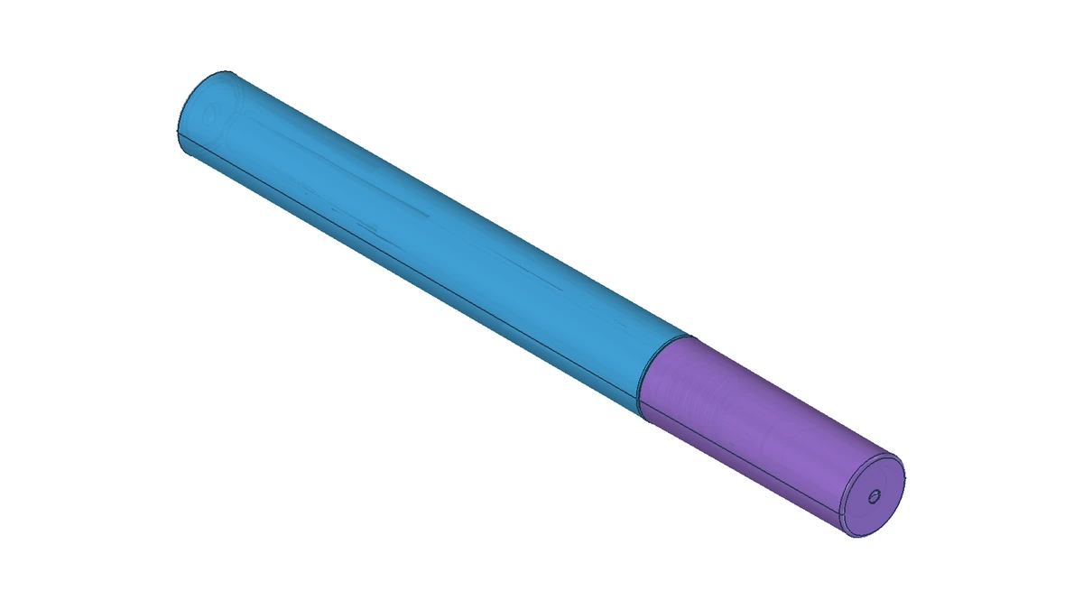
The YR7096A makes the decision easier to explain. It is one of Sambound’s existing Vỏ son bóng, but its part breakdown does not represent every lip gloss package. For this type of project, Sambound reviews design, tooling, molding, decoration, and assembly on the same component list. “Mold the cap separately” ultimately means deciding which parts remain and which parts must be remade.
What Information Is Needed Before Cap Tooling?
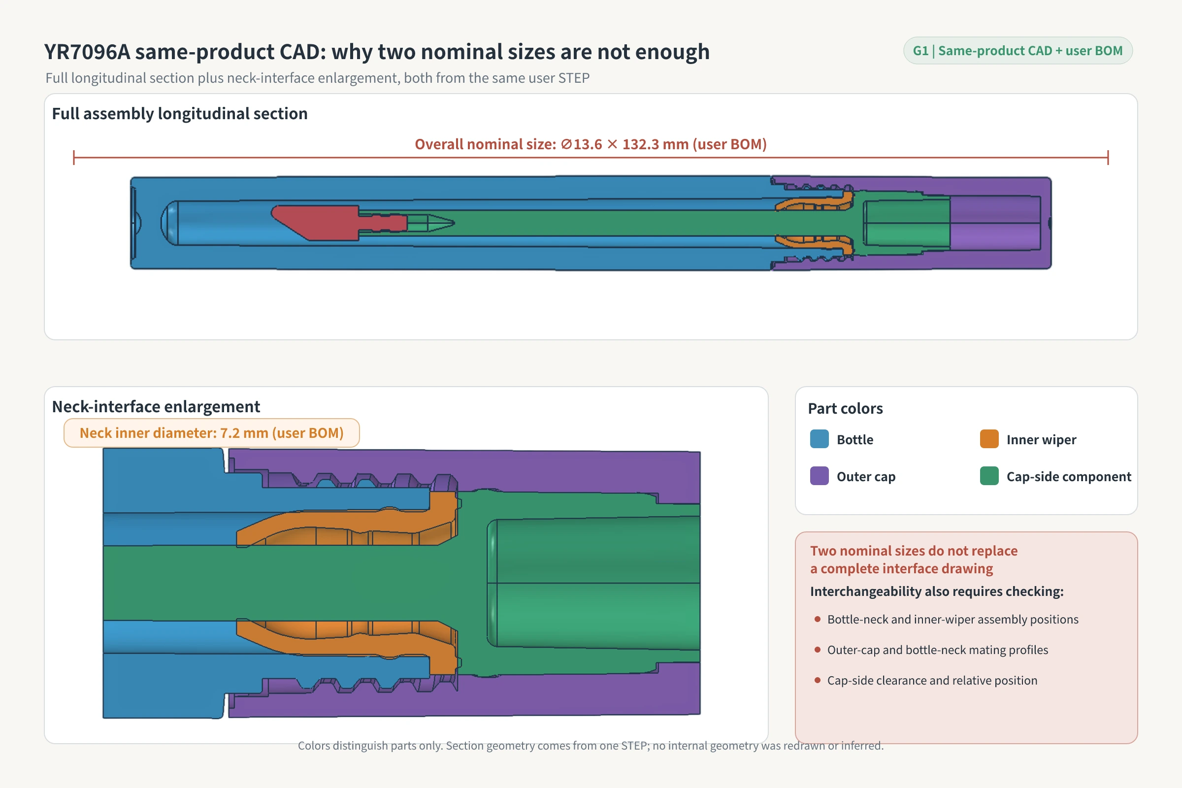
The first-party bill of materials (BOM) for the YR7096A confirms four main parts. The “support frame” below is the company’s BOM name for a cap-side part. Its exact function still requires an exploded view or section drawing, so it should not be assumed to be the wand stem. The wiper insert sits inside the bottleneck. The wand stem and applicator tip pass through its center opening, which removes excess product.
| Part code | Part name | Chất liệu | Mold record |
|---|---|---|---|
| YR7095AA | YR7095 A cap | ABS+AS | 16 cavities |
| YR7096FA | Support frame | PETG | 16 cavities; shared mold base with a new ejector sleeve |
| YR7095MA | Wiper insert | DE45D348 (company BOM material code; base resin not confirmed) | 16 cavities; shared mold base with new front and rear mold cores |
| YR7096BA | Bottle | PETG | 16 cavities; record of a shared mold base |
The mold base is the supporting frame that carries the cores and other molding components. Sharing a mold base does not mean sharing a complete mold. An ejector sleeve is part of the mold’s ejection system. The new ejector sleeve recorded for YR7096FA shows that its ejection arrangement required a separate adjustment; it does not show that the complete mold can be reused.
The customer-supplied BOM gives a nominal overall size of ∅13.6 × 132.3 mm. The ∅13.6 figure is not a bottleneck specification and should not be treated as the maximum outside diameter measured from CAD. The neck inside diameter is 7.2 mm, and the bottle length is 92 mm. A 7.2 mm neck opening alone cannot establish whether the cap, wiper insert, or wand stem is interchangeable. The 3.6 ml in the project name is the project’s product designation. The 3.5 ml in the BOM is the overflow capacity (OFC), meaning the maximum volume when the container is filled to the neck opening. These two figures describe different things and are not interchangeable.
A BOM identifies the parts, but it is not a controlled interface drawing for tooling release. The missing information includes the neck thread profile, thread lead-in point, and tolerances; an exploded cap assembly with each component’s function identified; separate wand-stem and applicator-tip data; and the actual sealing contact surfaces. A neck cannot be defined by one circular opening or one diameter. Its interface also includes the thread outside diameter, neck outside diameter, inside diameter, the location where the thread begins, and the neck height. The drawing, therefore, needs the complete T, E, I, S, and H dimension set. T is the maximum thread outside diameter, E is the neck outside diameter, and I is the neck inside diameter. S is the distance from the top sealing surface to the start of the first thread turn, and H is the neck height. Even if one neck dimension is the same on two bottles, that proves only that one value matches. The complete interface must still be compared before the cap, wiper insert, or wand stem can be called interchangeable.
If this information is incomplete, the correct decision is to pause the tooling release, not to “try the mold and see.”
The Changed Part Determines the Tooling Scope
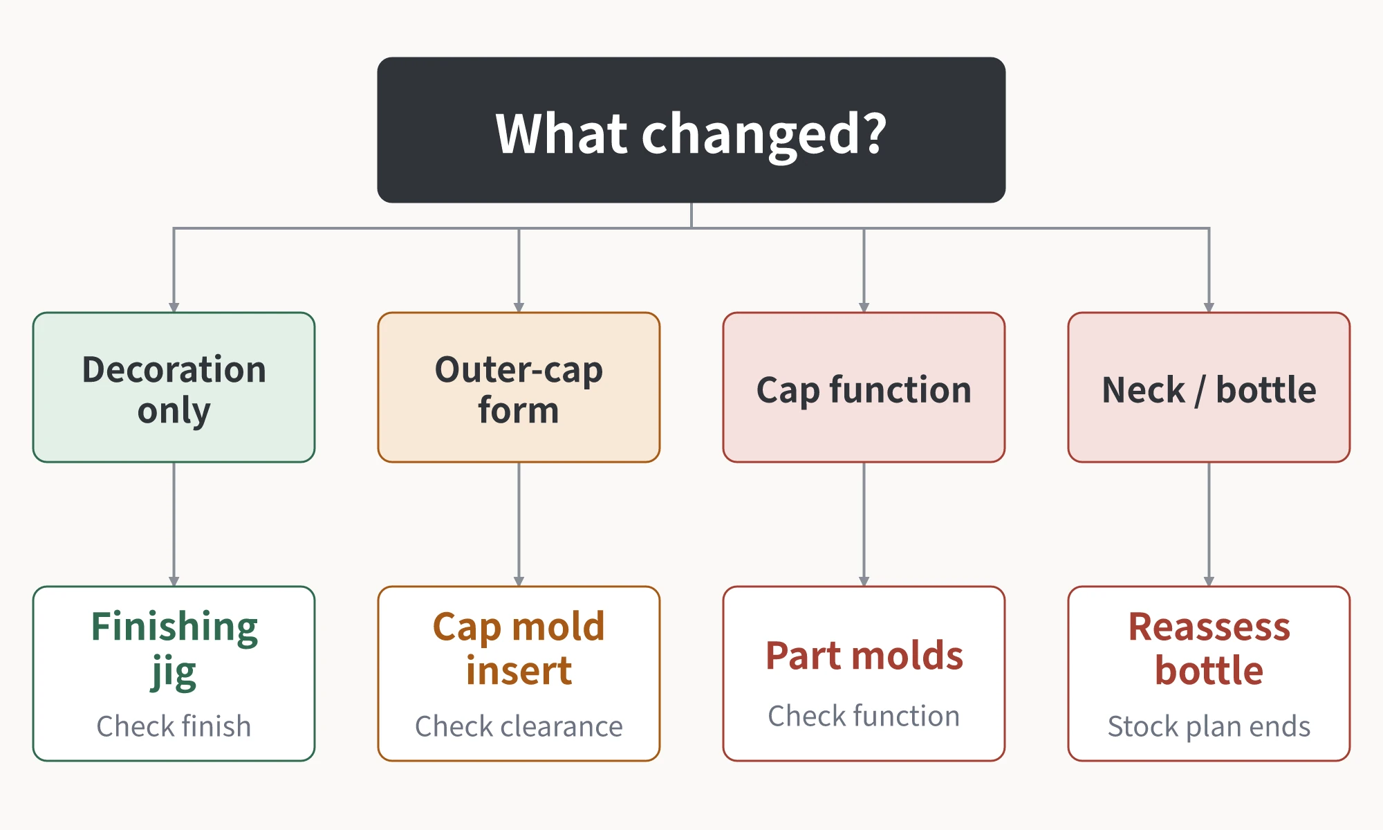
The tooling scope depends on the part that actually changes. The amount of customization is not a substitute for a component-by-component review.
| Change | Tool or mold usually affected | What still needs validation |
|---|---|---|
| Color, screen printing, hot stamping, or surface finish on the existing cap | Locating fixtures for downstream processes; normally no new structural mold | Adhesion, masking of uncoated areas, assembly scuffing, and interference caused by coating buildup |
| Outer-cap shape | Outer-cap mold or local inserts | Interference with existing internal parts, demolding, gate position, outer-cap axial height, and assembly jamming |
| Cap-side parts such as the support frame or threaded stem, or the wand stem or wiper insert | One or more new or modified molds, based on the actual part breakdown | Where the cap stops, which mating surfaces seat against each other, the axial positions of internal cap parts, whether the wiper remains in the neck when the wand is withdrawn, and whether the applicator tip passes through the wiper opening |
| Bottle neck or bottle body | Reassessment of the bottle mold and all mating parts | The original assumption of retaining the stock bottle no longer applies |
The YR7125A and YR7125B provide an internal comparison. Their cap assemblies require two separate injection molding operations: the threaded-stem/support-frame part is molded first, and the cap is molded second. At the same time, these models share a wiper insert, bottle, or mold base across product numbers. This comparison shows that a cap assembly can contain multiple parts made in separate molding operations. It does not prove that the YR7096A has the same breakdown, and “two injection molding operations” should not be rewritten as same-machine two-shot molding.
Which Part Should Be Checked When a Sample Fails?
A cap that screws on only shows that the design can move to further validation; it does not approve the complete package. Sample validation needs a complete lip gloss package with all matching parts, the project’s target fill volume, and the actual formula. The test environment, duration, closing and opening torques, sample size, and acceptance limits must come from the project specification rather than generic numbers.
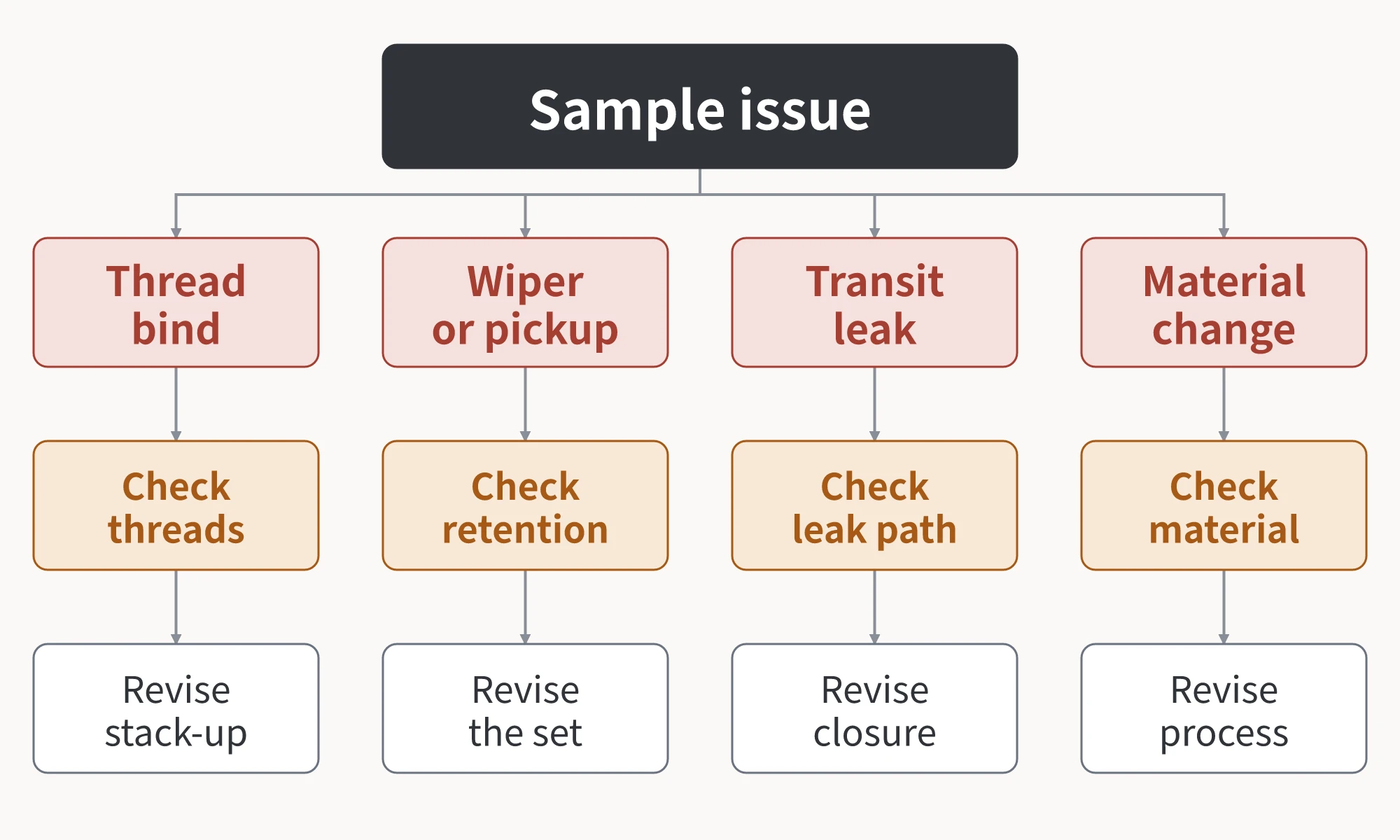
If the cap jams, cross-threads, tilts during engagement, or shows abnormal torque, first check the thread profile and tolerances, the thread lead-in point, and the axial stopping positions of the cap-side parts. Do not assign the problem directly to the outer-cap shape.
If the wiper insert is pulled out with the wand, first check whether it is retained securely in the bottleneck. Then check the resistance as the wand stem and applicator tip pass through the wiper opening. If too much or too little product is wiped off, review the wiper opening, wand stem, and applicator tip together. Changing only one of them can leave the applicator unable to pass through the opening.
If leakage appears after inversion, side storage, or the project’s specified simulated distribution test, identify the contact surface through which the formula actually travels. Then inspect the wiper insert, the mating stop surfaces, the cap, and the bottle. Sealing locations vary with the structure; there is no universal fixed “three-seal” model that can be applied to every package.
If contact with the actual formula causes cracking, softening, or swelling, first review the contact medium and each component material, and ask the molding supplier to check residual internal stress after molding. Increasing or changing the outer-cap axial height or revising the logo artwork cannot replace a material-compatibility investigation. This first-check sequence sets the order of diagnosis; it does not prove that any one item is already the root cause.
Conclusion: Release Tooling Only After the Interface Is Defined
The project has two gates. Before tooling, use the complete assembled sample, BOM, and controlled interface drawing to review the part breakdown and interface feasibility. A “stock bottle plus separately molded cap” can proceed to a mold trial only after confirming that the stock neck, wiper insert, and cap-side connection conditions can remain. After the mold trial, validate engagement, wiper retention, wiping performance, leakage, and material compatibility with a complete package, the target fill volume, and the actual formula. Mass production should be released only after the project’s acceptance criteria are met. If the information is incomplete, pause. If the sample fails, revise according to the observed symptom. If the neck or bottle must change, reassess whether this stock bottle is still the right base.